EXOSTIV Blade
Deep Multi-FPGA Capture. Remotely. At speed.
Applications
Pre-silicon SoC validation on FPGA prototype
Complex multi-FPGA Debug
Parallel FPGA system testing with multiple sites, targets and users
Capabilities
- Millions nodes capture from multiple FPGAs
- Up to 800 MHz sampling in FPGA
- Up to 4.5 Tbps bandwidth for 5.12 TB trace storage in a single unit
- Scalable bandwidth and storage resources
- Access FPGA prototypes from multiple locations
- Compatible with any FPGA prototyping system
Exostiv Blade: a no-compromise deep trace buffer for all your debug and test needs.

Features
- AMD FPGA support
- RTL, netlist and post P&R (ECO) insertion
- Connects to FPGA transceivers at 28.125 Gbps
- Compact, 2U and 4U modular chassis available
- Simultaneous capture from multiple FPGA at target speed of operation
- Multi-user capable host
- Client application for remote control (Win 64 & Linux)
- Python for automation, post-processing & use in CI environment
- Waveform viewer for local and remote waveform databases
- Merging utility for waveforms from multiple sources and clock domains
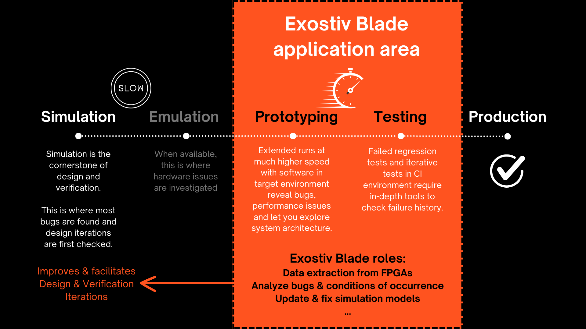
Exostiv Blade usage
Exostiv Blade is utilized for software deployment on FPGA prototypes, pre-silicon validation, and pre-production tests of SoC prototypes and FPGA systems, capturing extensive data directly from running FPGAs.
It aids electronic engineers in scenarios such as:
- Realistic testing environments
- Performance verification
- Regression testing for IP revisions
- Debugging issues not detected during simulation
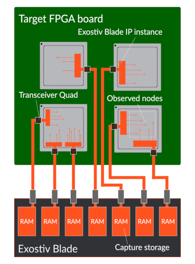
A flexible architecture
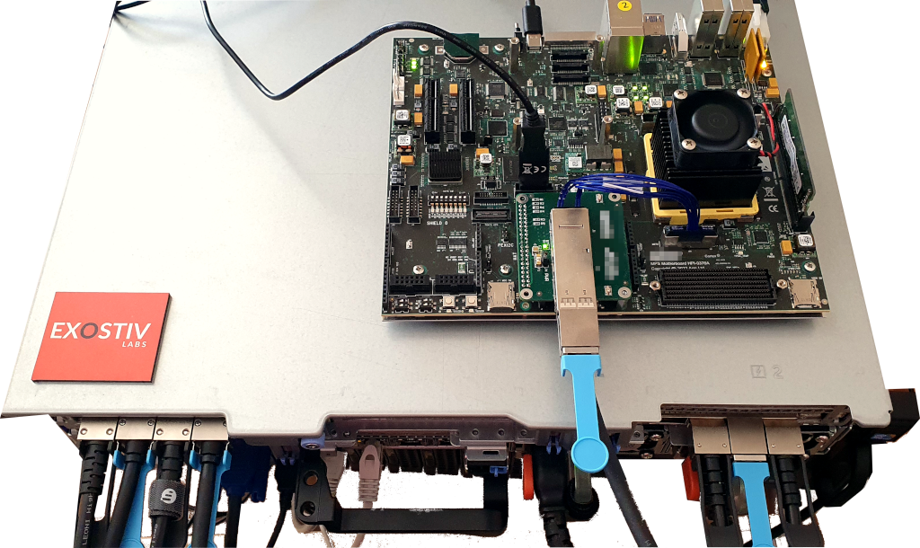
Exostiv Blade is composed of a chassis equipped with one or multiple capture boards. This architecture enables many configurations that adapt to the capture scenario.
Multiple FPGAs from multiple boards can be instrumented with capture IP instance that sample data directly from the design. Each of these instances use from 1 to 4 FPGA transceivers connected to the Exostiv Blade capture boards. The capture boards feature multiple quad tranceiver inputs in QSFP28 form factor used to transport the sampled data from the FPGAs under test to the Exostiv Blade hardware. A storage memory is attached to each of these connectors to receive and store the data.
This principle allows an extremely flexible scaling:
- Any number of FPGA chips from any number of boards can be instrumented.
- Each FPGA can contain multiple capture IPs.
- The Exostiv Blade unit is based on compact, tower, 2U to 4U chassis
- Depending on the chassis, from 1 to 10 capture boards can be used in the Exostiv Blade unit.
- Each capture board features 4x QSFP28 connectors, providing up to 4x 112.5 Gbps bandwidth using up to 16 transceivers.
- Each QSFP28 connector is attached to 16 GB up to 64 GB memory for trace storage, enabling very deep capture capabilities.
Exostiv Blade Range
Connectivity
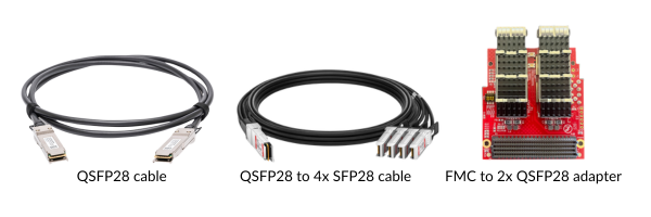
Exostiv Blade connects to FPGA chips transceivers. The standard connectivity is QSFP28, supporting up to 4 transceivers at 28.125 Gbps each (up to 112.5 Gbps per connector).
Compatible connectivity such as QSFP+ and connecting with adapters are supported – provided the bandwidth capabilities of the chosen interface.
Devices and Platforms
Supported FPGA devices* | AMD devices families: AMD Artix™ 7, AMD Kintex™ 7, AMD Virtex™ 7, AMD Zynq™, AMD Ultrascale™, AMD UItrascale™+, AMD Versal™ | |
Exostiv Probe connectivity | QSFP28, QSFP+, SFP28, SFP+, Samtech ARF-6 | Other connectors with adapter. |
PC connectivity | Over network | |
PC requirements | min. 8GB RAM available | |
OS Support | Windows and Linux | Win 64 versions 10 and 11. |
Exostiv Blade IPs overview
Exostiv Blade offers a range of IP types tailored to accommodate diverse capture scenarios.
Exostiv Blade Standard IP offers unparalleled flexibility, heightened interactivity in capture scenarios, and the fastest sampling speed, reaching up to 800 MHz.
With Exostiv Blade Extended Width IP*, users can achieve the widest reach of up to 65k nodes while minimizing the impact on FPGA resources. By integrating multiple instances of either Exostiv Blade IP, users can expand their node coverage even further within a single or across multiple FPGAs. Each IP instance uses from 1 to 4 FPGA transceivers.
Standard IP
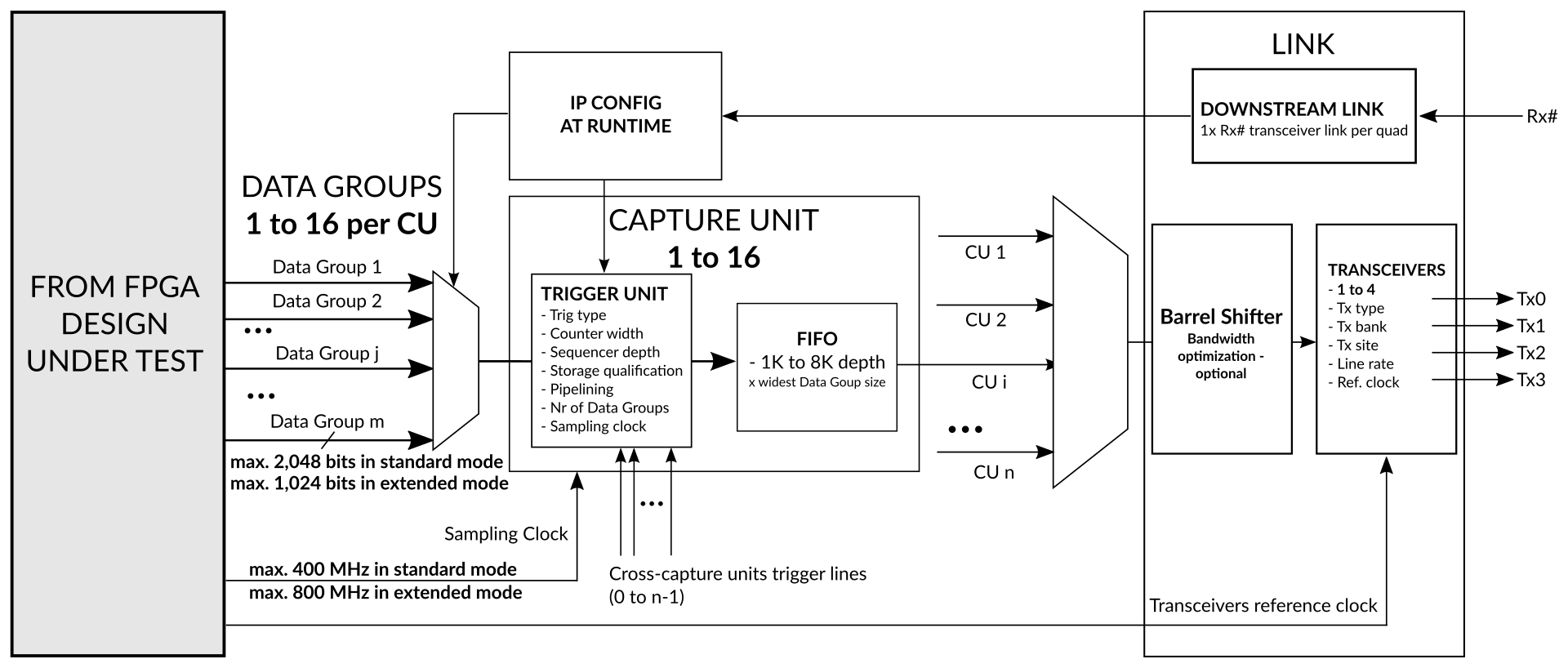
Main features include:
- Multiple capture unit with distinct sampling clock source
- Sampling up to 800 MHz
- Up to 16 x 2K bits simult. sampling per IP core instance
- Multiple data groups with dynamic selection at runtime
- Cross-clock domain triggering and data qualification
- Trigger positioning across the whole Exostiv Probe capture memory
- BRAM-based and Streaming (DDR based) modes of captures
Extended width IP
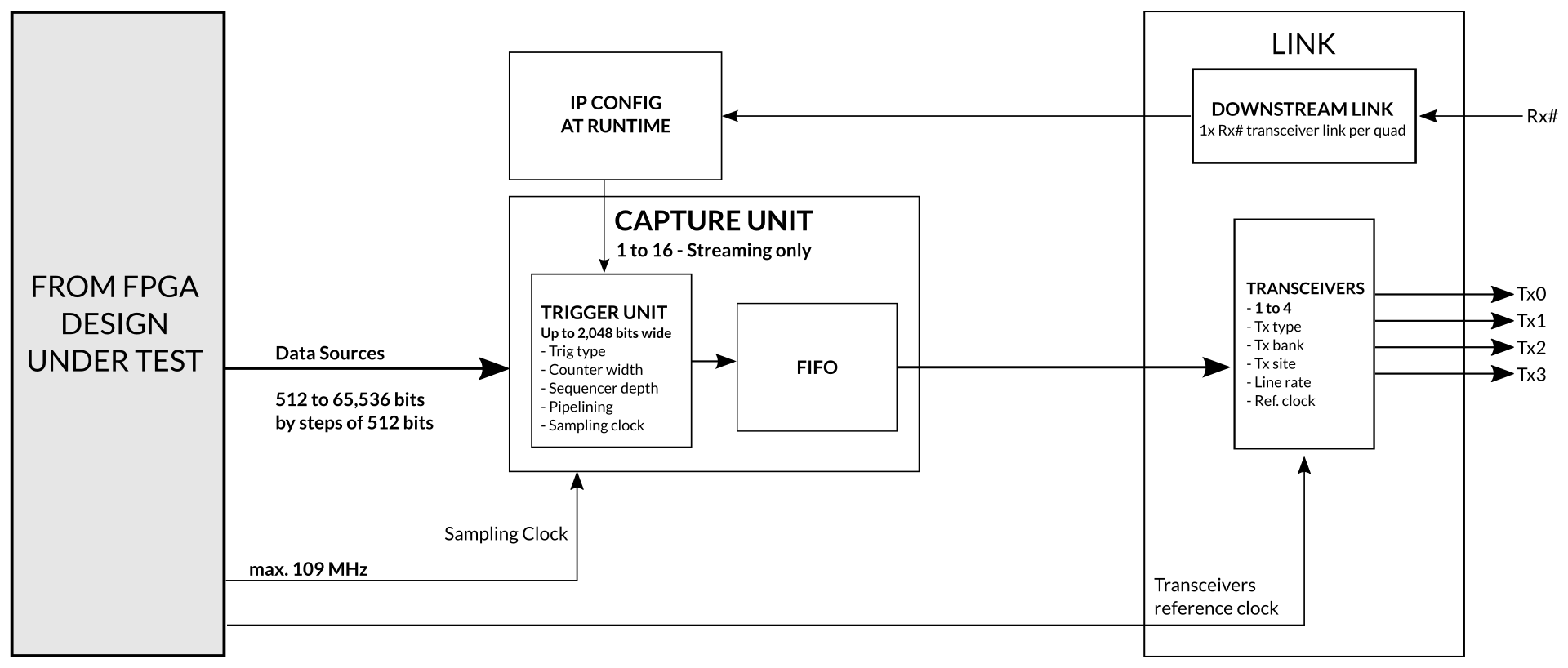
Main features include:
- Multiple capture units with distinct sampling clock source
- Sampling up to 109 MHz
- Up to 65K bits simult. sampling per IP core instance
- Extremely small footprint.
- Triggering on up to 2,048 inputs
- Trigger positioning across the whole Exostiv Probe capture memory
- Streaming (DDR based) mode of capture
Exostiv Blade IPs are configured, generated and inserted with the Exostiv Blade Core Inserter software. Exostiv Blade Core Inserter includes controls used to:
- Select the IP type.
- Define the location and settings of the FPGA transceivers used by the IP instance.
- Define the features and FPGA resources used by the IP.
- Set up the inputs ports of the IP instance and possibly select the observed nodes from the design under test.
- Generate and potentially insert the IP core into the target design.
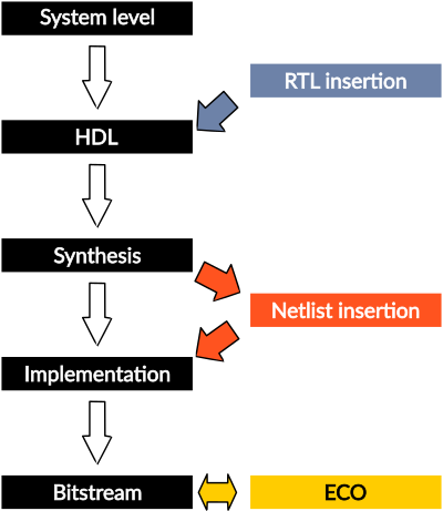
IP insertion flows
Exostiv Blade core inserter enables IP generation, insertion and modification at 3 levels:
- RTL level: Exostiv Blade IP instances are generated as a synthesized netlist with a VHDL or Verilog wrapper, design constraints and insertion template. The IP is inserted into the target design by the user like any other part of the design. Afterwards, the whole design has to be synthesized and implemented by the user. This mode of insertion provides full control to the user for insertion in the source code.
- Netlist level: (AMD FPGA only) Prior to proceeding with this type of insertion, the user has to load a post-synthesis design checkpoint in the FPGA vendor tool. Exostiv Blade Core Inserter interacts with the vendor tool to select the sampling clock signals and the nodes to be observed with the Exostiv Blade IP instance. Thereafter, Exostiv Blade IP instances are synthesized and automatically inserted into the target design netlist. This is followed by automatic or manual implementation (P&R) and bitstream generation.
- ECO (Engineering Change Order – AMD FPGA only): This special level enables late modifications of the connections between a specific IP instance and the design under test. Prior to proceeding with it, the user has to load a post place and route DCP into the vendor tool. Exostiv Blade core inserter interacts with the vendor tool to modify the existing connections with the FPGA under test. When the Exostiv Blade IP resources need not to be modified, this mode provides the fastest turnaround time to observe new sets of FPGA nodes.