Search
What are the switches for on the FMC to HDMI adapter? (Legacy / EOL)
As defined in the ANSI VITA standard, the HDMI to FMC module (EA-HDMI-FMC-01) must provide the reference clock for the transceiver links. For this purpose, a low-jitter dual output oscillator is mounted on the plug-in adapter. The output frequency of the oscillator is digitally selected and can be changed by the user using the on-board DIP switch.
The 2 generated clock signals are LVDS differential pairs and must be terminated to 100 Ohm resistor on the destination board. This termination resistor is usually available as an internal differential termination inside the target FPGA.
Refer to the figure below for the definition of the DIP switch indexes. Please pay attention to the respective position of the ‘ON’ (‘1’) and ‘OFF’ (‘0’) for the switches.
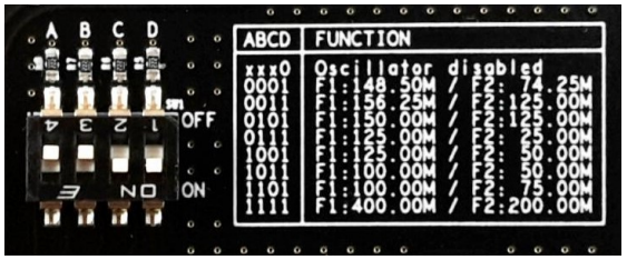
F1 and F2 as labelled on the picture above represent the programmed values for ‘GBTCLK0_M2C_P/N’ and ‘GBTCLK1_M2C_P/N’, as usually used on such FMC adapters.