Search
How do I update the MICA board configuration? (Legacy / EOL)
The ‘MICA’ board is a demonstration board mounted with an Xilinx Artix-7 FPGA. This board can be used to get started with EXOSTIV, as it is loaded with an example design instrumented with an EXOSTIV IP.
Please contact us to receive the reference project file (.epf), documentation and Vivado reference project.
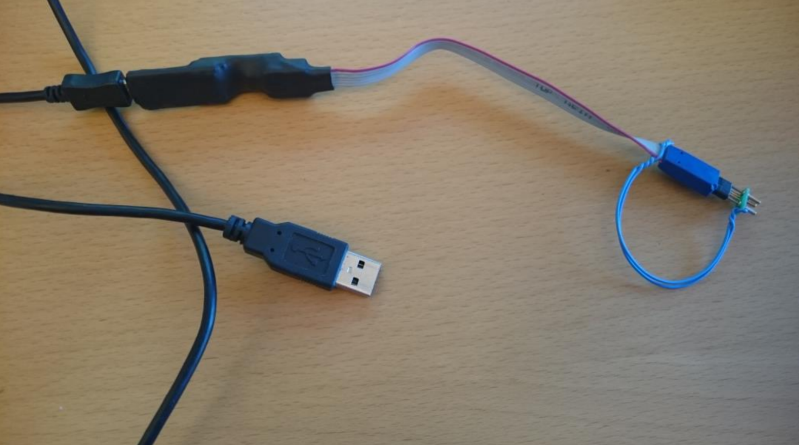
The MICA board is provided with a programming cable that has to be used to update the FPGA or FPGA EPROM configuration.
To update the FPGA or the EPROM configuration, proceed as follows:
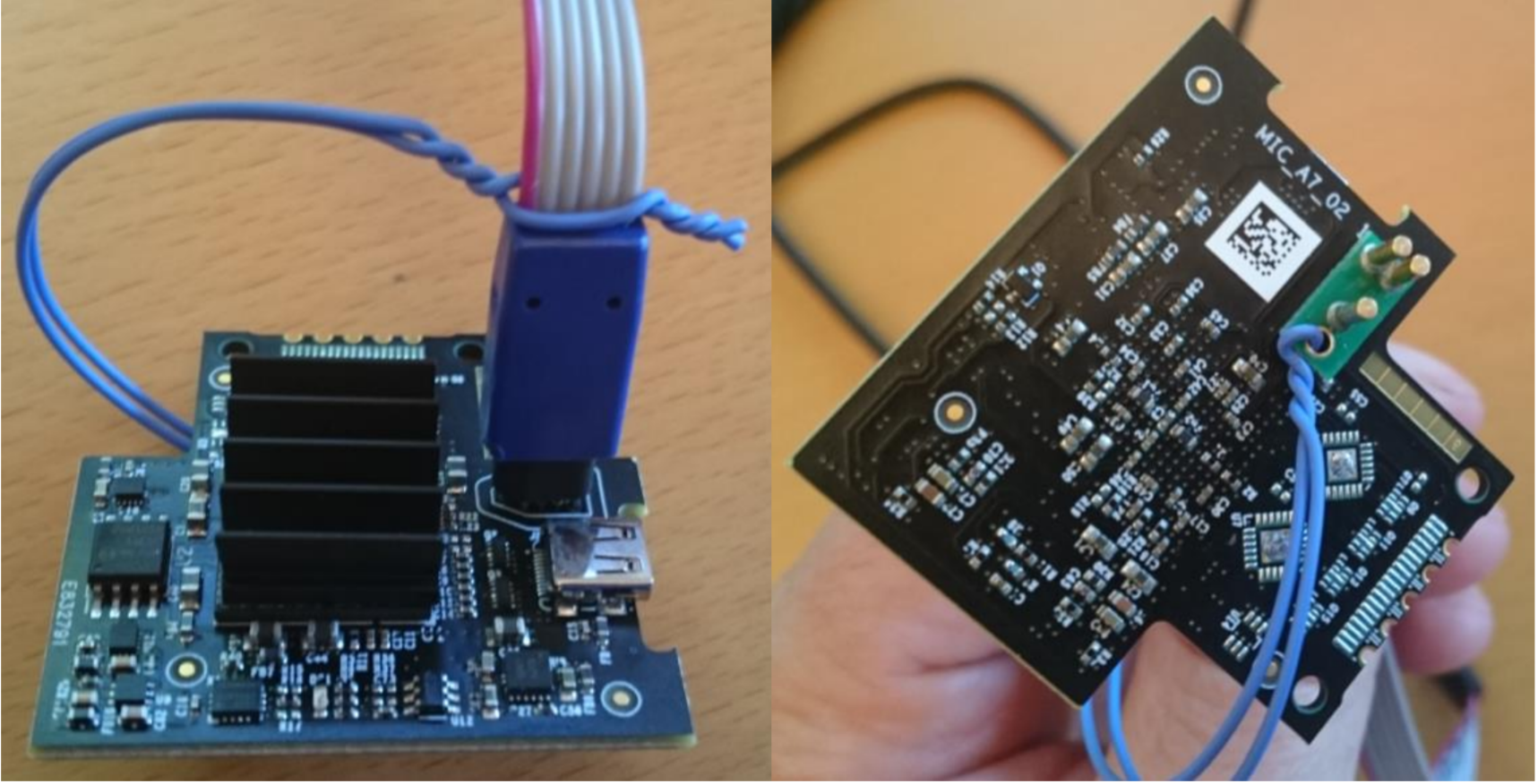
1) Connect the provided programming cable to the MICA board as shown below:
2) Connect the other end of the programming cable to your workstation with the proper USB cable.
3) Power-up the MICA board. The MICA board is powered through the EXOSTIV probe:
– Plug the HDMI cable into the HDMI-to-micro HDMI adapter and this one to the MICA board.
– Connect the other end of the HDMI cable to the EXOSTIV Probe.
– Connect the EXOSTIV probe to the PC with the USB cable.
– Open EXOSTIV Dashboard and power-up EXOSTIV probe
– Open the MICA project file in the EXOSTIV probe (it would be: demo_mica702-3link*.epf)
– Connect the PC to the EXOSTIV probe using the EXOSTIV Dashboard ‘connect’ button.

(Then, hit on ‘connect’ in the pop-up that opens:)
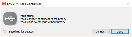
When doing so properly, a red LED with light up shortly on the MICA board.
The log can report that it cannot connect properly – please disregard this.
4) Start Vivado ‘Hardware Manager’ and Open the target board.
5) Locate the desired .bit or .bin configuration file and program the FPGA device – or:
6) Add the configuration device to the chain: select model ‘N25Q128A11ESE40G’ (SPI serial flash, 1x 2x 4x and DDR, 128 Mb from Micron, 1.8V – appears as ‘n25q128-1.8v-spi-x1_x2_x4’ in the Vivado Hardware Programmer interface) – and program this device with the .bit or .bin file.