Why do I get an ‘overflow’?
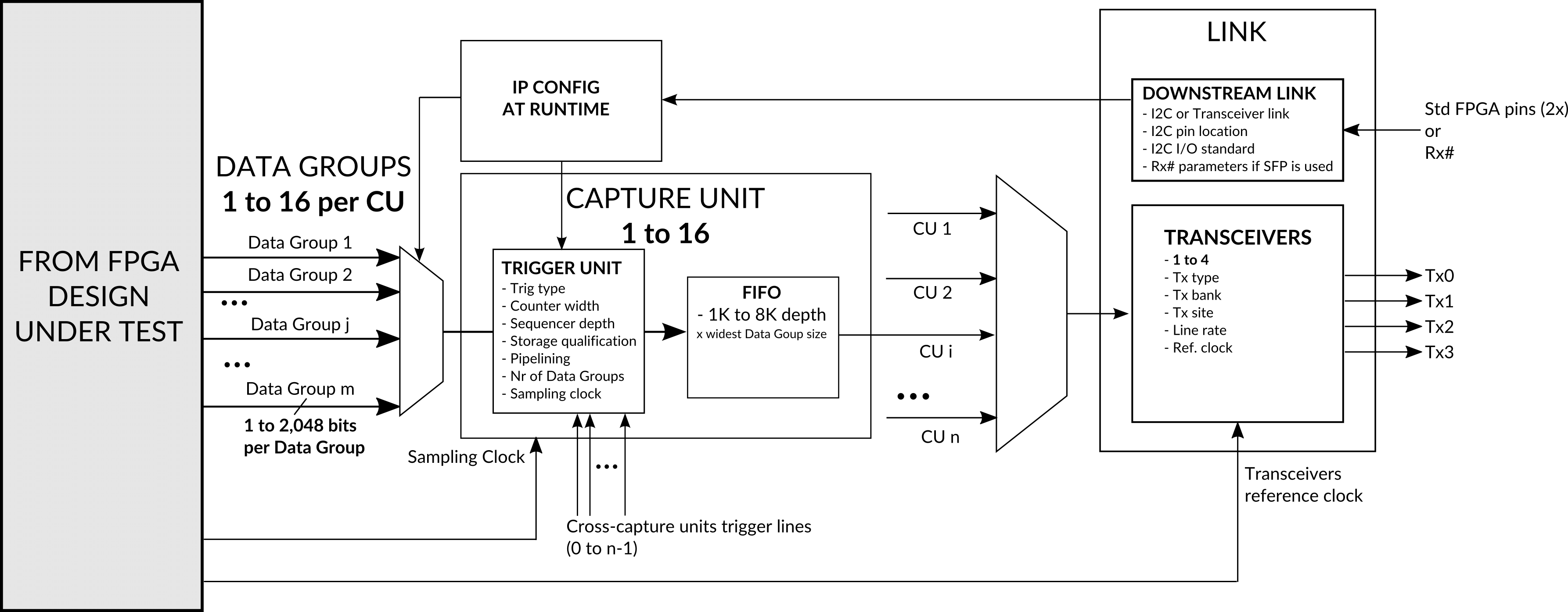
Overflows are reported by capture units when your capture requires more bandwidth than what is available from the transceivers.
The bandwidth required by a capture depend of:
– The capture unit width: thisis the size in bits of the largest data group connected to the capture unit.
– The sampling clock frequency: the rate at which data is sampled.
– The capture sizes, the trigger and data qualification settings: these settings lead to capture chunks of data repeatedly (‘interrupted captures’) or to capture data continuously. This results in modulating the average bandwidth required for the capture.
The bandwidth available for extracting data to EXOSTIV Probe depends on the number of transceiver used and their data rate.
Once the bandwidth required by the capture exceeds the bandwidth available at the transceivers, an overflow is reported and the capture stops for the related capture unit.
– ‘How many nodes can I sample continuously without creating overflows’
– ‘Debugging FPGAs at full speed’: discusses the strategies for making the most of EXOSTIV’s resources.
IP configuration and resources should be chosen carefully in order to reach the debugging scenario’s goals. For instance:
– It can be interesting to connect a limited number of bits to a capture unit, that can be captured without interruption with the bandwidth available at the transceivers. For instance, key control signals from system busses, that allow observing the general behavior of the system and track global dysfunctions.
– Conversely a capture unit connected to a lot of bits provide lots of details during very limited time – as continuous capture are not be possible. For this capture unit, it can be advised to use a deeper FIFO buffer, in order to enlarge the burst that can be captured without overflow.
– Such ‘capture strategies’ can be used together, with the first capture unit sending a trigger to the second.
… and so on.


