EXOSTIV software v1 – EXOSTIV Dashboard (EOL / Legacy product)
This page contains information for End-of-Life (EOL) Exostiv products. This information is for historical reference only and does not reflect the performance of 2026-generation hardware and software.
* The information on this page is about Exostiv Dashboard v1, using EP12000 or EP6000 Probes.*
EXOSTIV Dashboard software (Windows, Linux & MacOS) provides the tools to insert EXOSTIV IP into the target FPGA and analyze trace data captured from FPGA at runtime. EXOSTIV Dashboard is composed of the Core Inserter and the Analyzer. EXOSTIV Core Inserter is used to setup, synthesize and optionally automatically insert EXOSTIV IP.
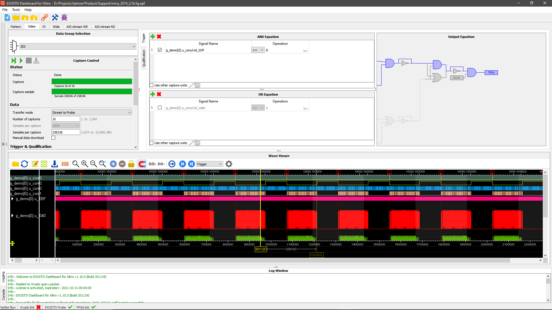
EXOSTIV Analyzer is used after the target FPGA is loaded with a design instrumented with EXOSTIV IP to capture data from the FPGA under test running on a board.
EXOSTIV Core Inserter: set up and insert IP
EXOSTIV Analyzer: capture and analyze data
The videos above are also available from Exostiv Labs’ Youtube channel
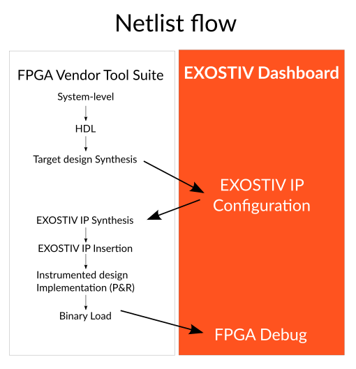
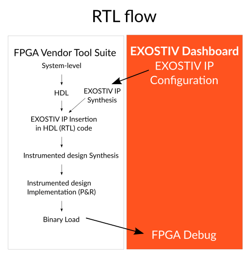
EXOSTIV Core Inserter is used to set up EXOSTIV IP and synthesize it with the help of the FPGA vendor tool. EXOSTIV IP is inserted into the target design at RTL or at netlist level.
In the netlist flow, EXOSTIV Core Inserter establishes a communication with the FPGA vendor tool. This enables the extraction of the hierarchy, nodes and clocks, from the target FPGA database. Once EXOSTIV IP resources and connections with the target FPGA nodes are defined, the Core Inserter adds EXOSTIV IP to the target FPGA design and requests the FPGA vendor tool to run implementation (place & route).
In the RTL flow, EXOSTIV Core Inserter uses the FPGA vendor tool to configure the parameters and resources of EXOSTIV IP and synthesize it, together with pinout & timing constraints, as well as RTL-level instantiation template.
Once the instrumented FPGA programming file is available and loaded into the target FPGA, EXOSTIV Analyzer can use EXOSTIV IP to capture data from the target FPGA and upload it to the PC for visualization and analysis.
Connecting EXOSTIV
Standard connectivity.
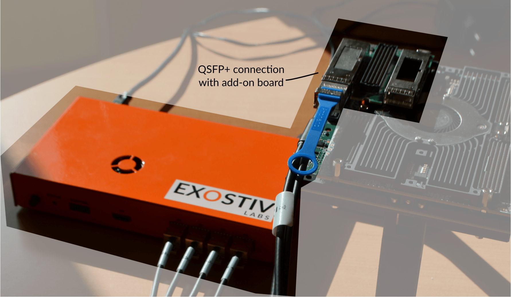
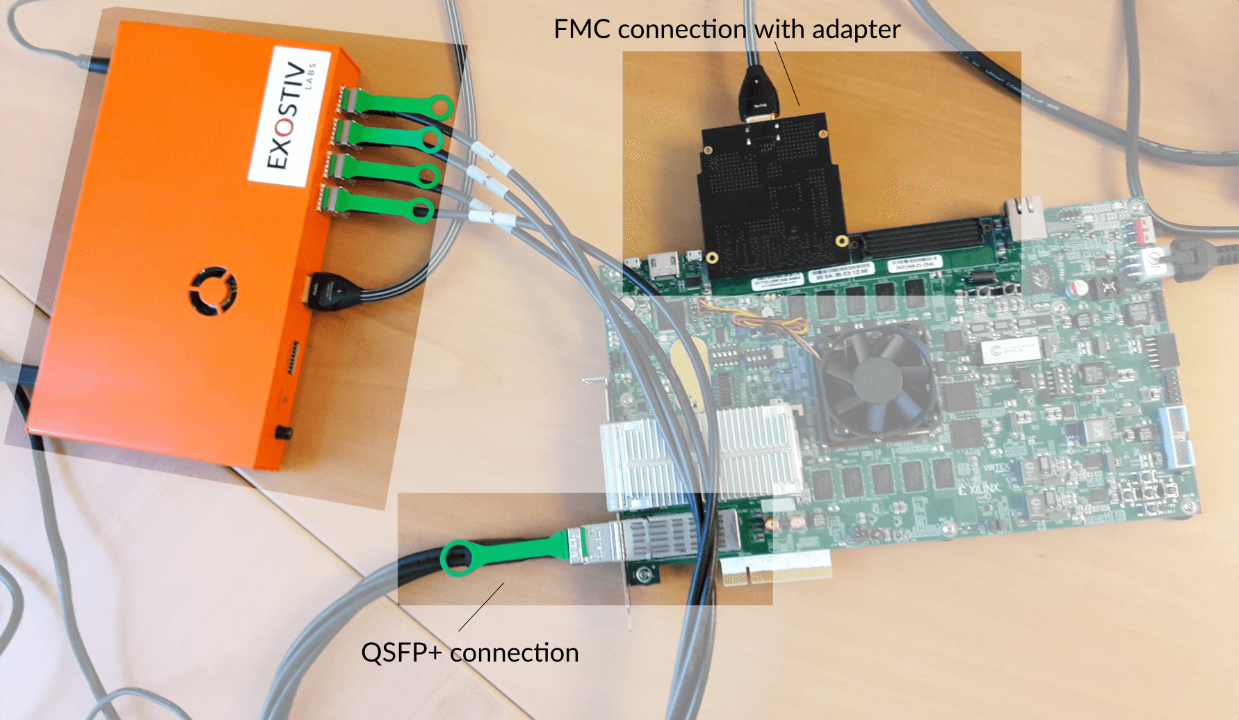
Exostiv probe connects to FPGA transceivers / SERDES at up to 12.5 Gbps with standard connectors available on many FPGA boards, including ASIC / SoC prototyping platforms.
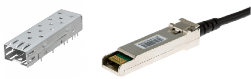
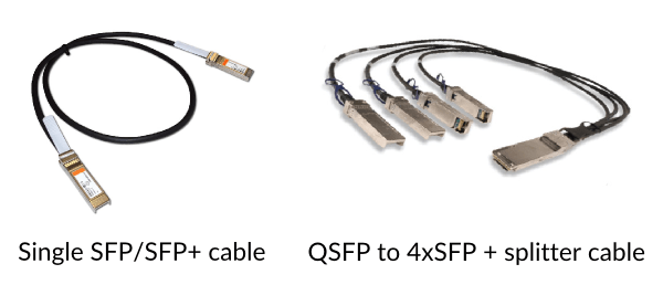
- SFP+ (copper or optical cables) – up to 12.5 Gbps per link;
- QSFP+ or QSFP28 (copper or optical cables) – up to 12.5 Gbps per link;
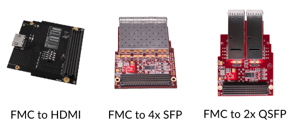
- FMC HPC and LPC with a plug-in adapter – up to 12.5 Gbps per link;
Custom connectivity.
Alternative solutions involve choosing another connector or use a mezzanine connector and making an adapter for it. The choice of a connector and adapter depends on your target board and constraints. Please contact us to find out about the best solutions.
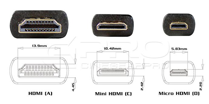
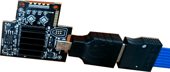
Important: Exostiv Probe connectivity included the usage of a ‘HDMI connector’ with a custom pinout for compact connectivity. Using this connector is not recommended for new designs. It will be supported as legacy for existing designs only. Please contact us to receive guidelines for compact connectors as we are updating our documentation.
Custom connectivity.
* NOT RECOMMENDED FOR NEW DESIGNS – Contact us *
Exostiv can also use HDMI type-A, type-C or type-D connector with a custom pinout in case you’d like to add a cheap & small footprint connector to your custom board.
- Compact / Reduced footprint on PCB necessary for debug.
- Right angle or vertical connectors available.
- High availability of connectors and cables.
- Limited impact on BOM costs.
Used at up to ~8 Gbps – 10 Gbps per link (size and board layout-dependent)
Require the transceivers and 2 addional standard pins on FPGA for IP downstream control.
Click here for an example of schematic for this type of connectivity(PDF)
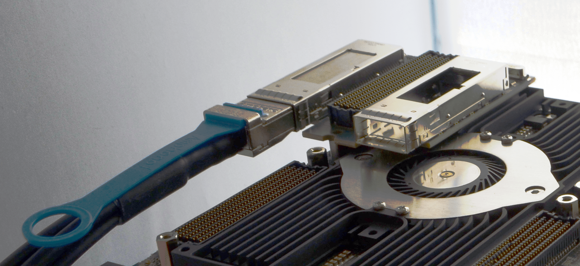 QSFP+ connectivity with add-on board.
Which connector works for you?
1. Is there an existing SFP/SFP+/QSFP/QSP+ directly connected to the FPGA transceivers?
- Check if you can reserve this FPGA resource (and the board connector) for debug – at least temporarily. You’ll need 1 SFP/SFP+ connection per used gigabit transceiver
- QSFP/QSFP+ connectors can be used with a 4xSFP to QSFP cable with splitter.
Note: most of our partners’ boards or FPGA vendor standard demo kits feature SFP/SFP+, quad SFP/SFP+ or QSFP/QSFP+ connectors by default. And they are directly connected to FPGA transceivers.
[divider]
2. Is there another type of connector directly connected to the FPGA transceivers?
- With a board adapter, you can use EXOSTIV
- FMC (‘FPGA Mezzanine Card’) is a good example. Exostiv Labs has created a HDMI to FMC module adapter that works with EXOSTIV. Many other FMC to SFP/QSFP adapters can be found commercially.
- Would you like to make your own adapter? We can help and review it with you.
Please contact us for details on our adapters, external references and custom adapters support.
[divider]
3. For all other cases: you’ll need to modify your board and add a connector.
Contact us and we’ll find the best solution for you.
You do not have space constraints (lucky you)? Pick the one you like: SFP/QSFP/other (+ adapter).
Quick links:
EXOSTIV IP
* The information on this page applies to EXOSTIV IP cores generated with Exostiv Dashboard v1, using EP12000 or EP6000 Probes.*
Please go to the respective product pages for information about the IP generated with software v2 for the EP16000 Probe or Exostiv Blade
The customizable EXOSTIV IP core is a logic analyzer core that can be used to monitor the internal signals of an FPGA design without having to store the full trace data in the FPGA. The EXOSTIV IP core uses the FPGA transceivers as a high bandwidth channel to an external memory (in EXOSTIV Probe). The EXOSTIV IP core must always be used together with the EXOSTIV Probe and EXOSTIV Dashboard software. The IP includes many advanced features for extending visibility on FPGA running at speed of operation- including data group definition and multiplexing, boolean trigger equations, data qualification (data filtering) and edge transition triggers. Because EXOSTIV IP core is synchronous to the design being monitored, all design clock constraints that are applied to your design are also applied to the components inside IP Core. EXOSTIV IP can be inserted at RTL level or automatically in the design netlist, thanks to the accompanying EXOSTIV Dashboard software.
Features
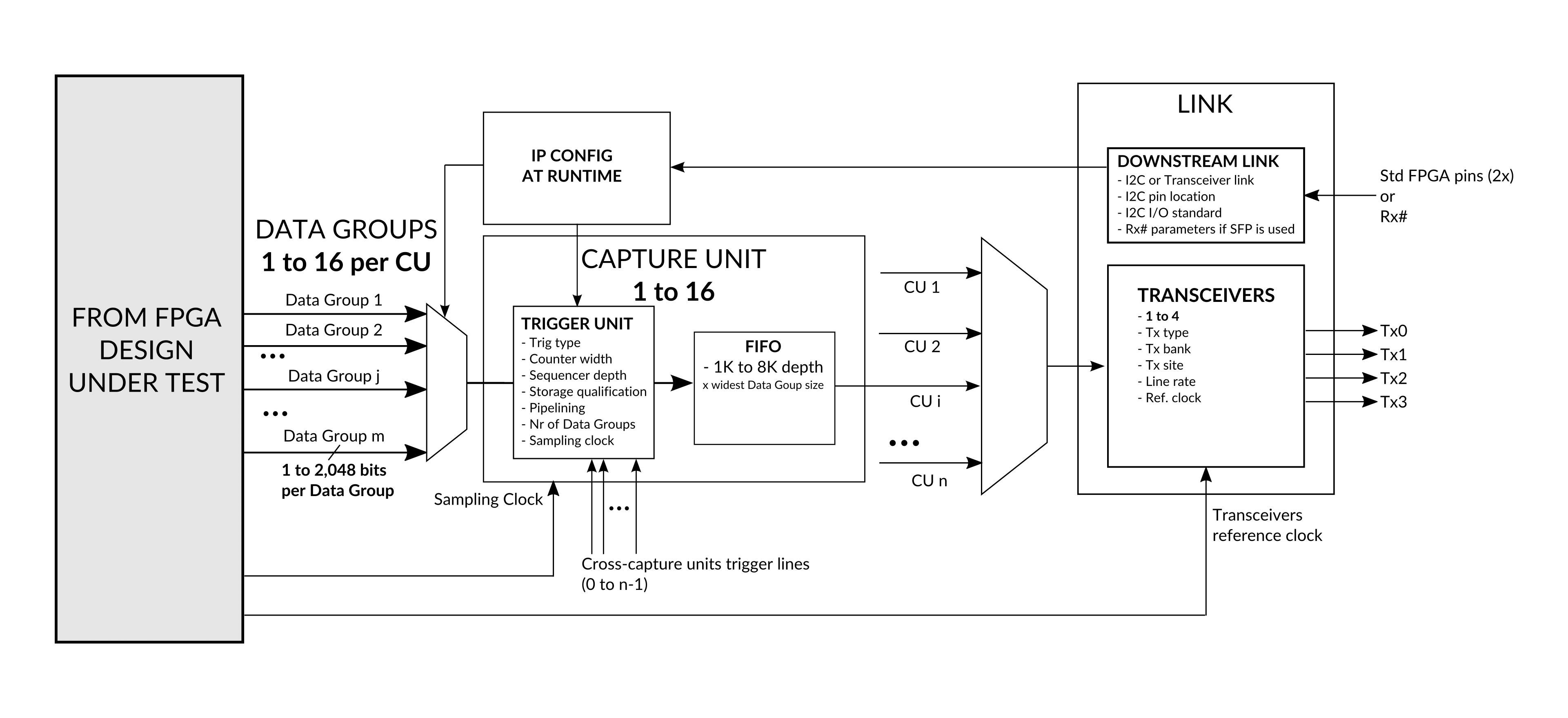
- Configurable upstream link, using 1 to 4 FPGA transceivers up to 12.5 Gbps located in the same quad or 6 pack.
- Downstream link to configure IP at run-time, without the need to re-implement instrumented design.
- From 1 to 16 configurable ‘Capture Units’ (CU) to sample FPGA internal nodes, with trigger and data qualification resources and selectable FIFO size.
- From 1 to 16 multiplexed Data Groups per CU, selectable at run time through downstream link.
- From 16 to 2,048 bits per Data Group, connected to the target FPGA internal nodes.
- Up to 390 MHz sampling in FPGA.
- Cross-Capture Units trigger lines.
- Limited footprint on FPGA resources – equivalent to the footprint JTAG embedded logic analyzers on the logic for equivalent number of nodes connected. Huge gain on internal memory – FPGA BRAM memory resources do not have to grow with the size of the capture.