Exostiv Blade Core Inserter is used to generate the Exostiv Blade IP cores used to capture data from inside FPGA chips with Exostiv Blade.
This application is installed on Windows and Linux workstations and uses the target FPGA vendor tool, which must be installed separately (not provided).
Exostiv Blade Core Inserter provides the following features:
- Libraries of the supported FPGA parts with pinouts and capabilities;
- Controls to set up the connectivity with Exostiv Blade;
- Controls to set up Exostiv Blade IP capture options and features;
- Controls to run Exostiv IP generation and insertion.
Exostiv Blade IP – Overview

Each Exostiv IP instance:
- uses at most 1 full transceiver quad (1 to 4 transceivers);
- supports transceiver data rates up to 25 Gbps (100 Gbps max per quad);
- allows sampling frequencies up to 800 MHz(depends on FPGA part capabilities and ability to place and route instrumented design);
- provides up to 16 ‘capture units’ (the logic used to sample data) with distinct size, triggering, buffering and clocking settings;
- captures up to 16 times 2,048 bits (up to 16 ‘capture units’) simultaneously;
- captures from up to 16 distinct clock domains;
- provides an ability to multiplex up to 16 data groups onto each capture unit;
- provides a communication channel from the Exostiv Blade to the IP instance to change capture parameters without the need to re-compile;
- allows cross-clock domain triggering.
Depending on the capture needs, multiple Exostiv Blade Core Inserter IP instances are generated for insertion into one or multiple FPGAs. Because each Exostiv Blade IP instance uses transceivers from the same target FPGA quad, there will be as many physical connections between the target system and the Exostiv Blade unit as there are Exostiv Blade IP instances. Each distinct Exostiv Blade IP instance has to be generated with Exostiv Blade Core Inserter software.
Exostiv Blade Core Inserter – Welcome screen
The welcome screen provides shortcuts to create or load project files (extension .bpf), in addition to license controls and direct access to online documentation (such as this article).

When creating a new project file the type of insertion flow is chosen:
- Netlist insertion flow: generates the Exostiv Blade IP instance and inserts it automatically into the target synthesized FPGA loaded in Vivado.
- RTL insertion flow: generate the Exostiv Blade IP instance with a template and constraint files ready for insertion into VHDL or Verilog code.
For more information about the netlist and RTL insertion flows, please refer to the following article: RTL or netlist flow?.
Exostiv Blade Core Inserter – Link configuration
The ‘link configuration’ page defines the target FPGA for the generated IP and how it connects to Exostiv Blade. This information is fully available in the specifications of the target FPGA board – and how it is set up.
The parameters are:
- FPGA Type: FPGA family, package, speed grade, part number.
- Upstream link: defines the bank, the number and the pin location of the transceivers used to connect the generated IP to Exostiv Blade.
- Downstream link: defines which of the chosen transceivers is used for the ‘downstream channel’ from Exostiv Blade to the IP.
- Reference clock: transceiver source clock characteristics. Location, frequency, derived line rate and PLL parameters.
- Downstream link rate: some information and parameters about the downstream link.

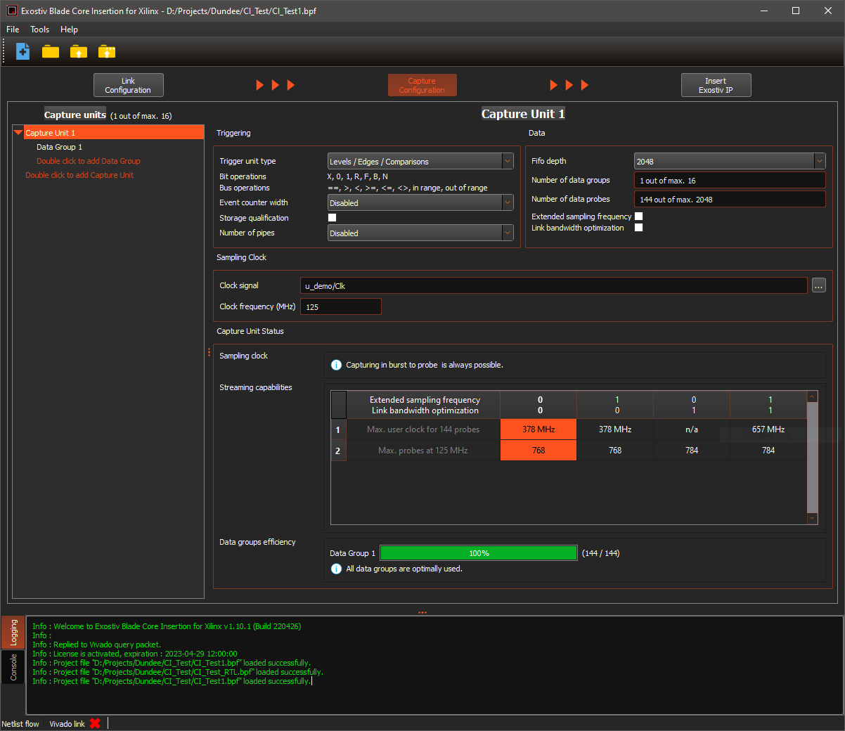
Exostiv Blade Core Inserter – Capture configuration
The ‘Capture Configuration’ screen provides the settings that define the resources of the IP used to capture (sample) data from inside the FPGA:
- The list of ‘capture units’ and the multiplexed data groups connected to each of them;
- For each capture unit, the allocated resources: trigger machine complexity, additional trigger counter and data qualification, capture unit FIFO / in FPGA buffer size, optional transceiver bandwidth optimization resources (barrel shifter).
- Sampling clock signal source (netlist mode) and frequency;
Moreover, the ‘capture configuration’ screen provides an analysis of the chosen option, and how they allow streaming data to the Exostiv Blade, provided the number of transceivers and their data rate (burst mode is always possible). For more information about the ‘stream to probe’ and ‘burst to probe’ modes, please check this article.
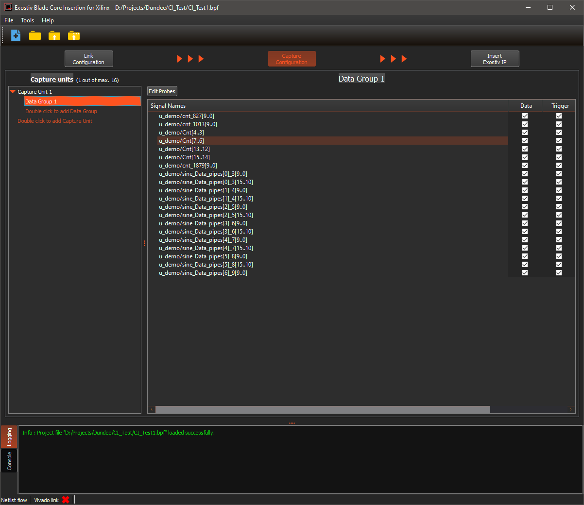
Selecting one of the data groups in netlist mode of insertion displays the controls to select the nodes to be observed from the synthesized design loaded in Vivado.
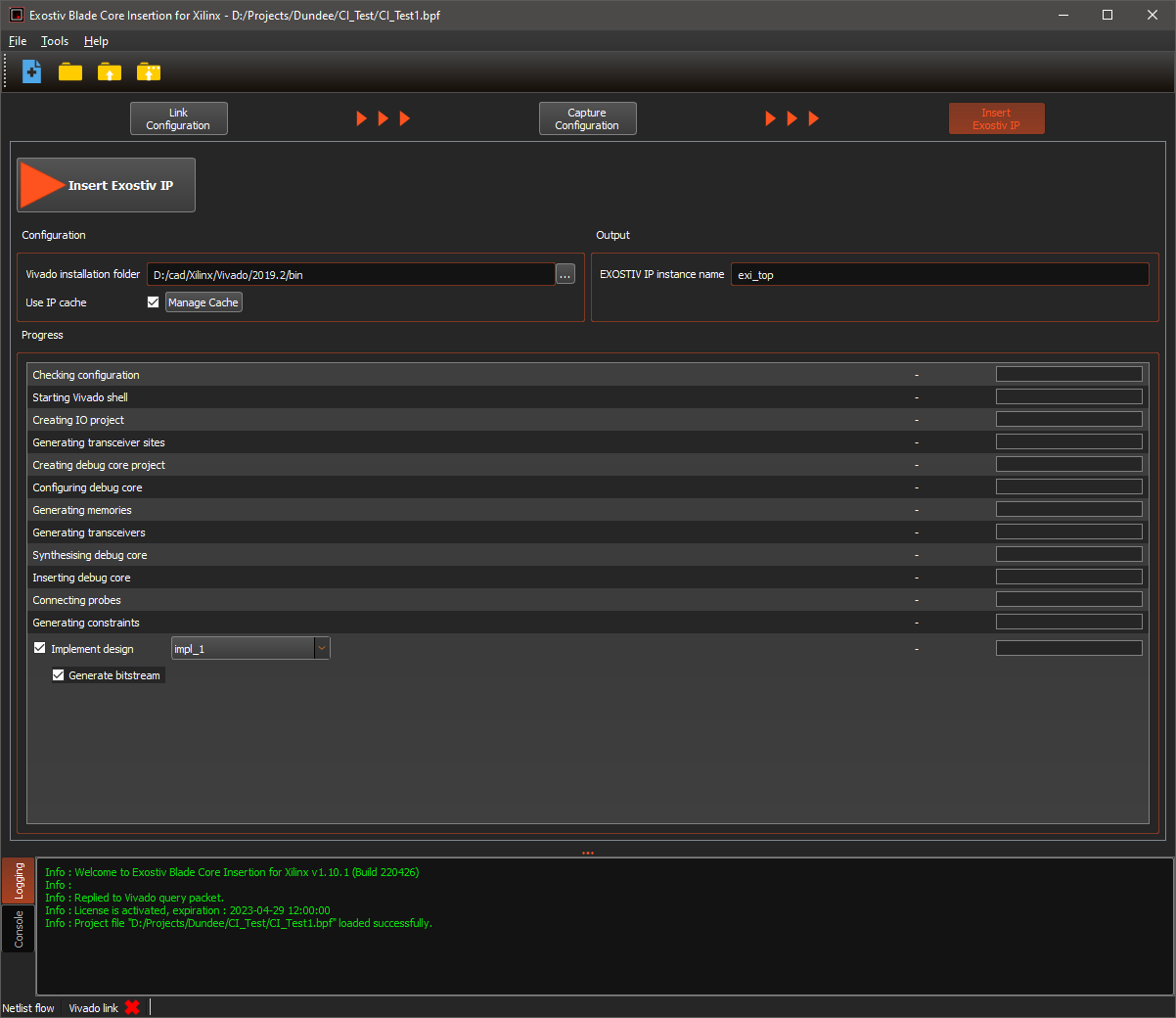
Exostiv Blade Core Inserter – Core Generation and Insertion
Finally, the last screen, which depends on whether netlist or RTL mode of insertion is used, allows running the following:
- RTL mode: generates an Exostiv Blade IP as configured and provides it as a synthesized netlist with additional files (wrappers, constraints, scripts). Please refer to the following article to learn about the files generated in RTL insertion flow by Exostiv Blade Core Inserter: Xilinx FPGA: which files are produced in RTL flow and how do I use them?
- Netlist mode: generates an Exostiv Blade IP as configured, inserts it into the synthesized design loaded into Vivado and connects the nodes chosen for observation. Optionally runs implementation (place and route) and bitstream generation.