RTL or Netlist flow?
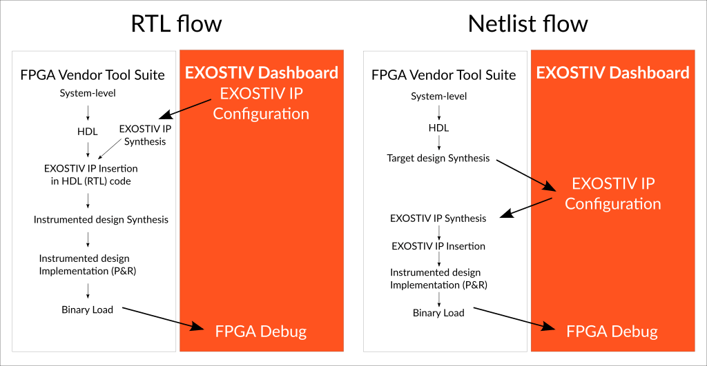
EXOSTIV Dashboard Core Inserter and Exostiv Blade Core Inserter propose 2 alternate flows* for inserting EXOSTIV IP and Exostiv Blade IP into the target design: the ‘RTL flow’ and the ‘Netlist flow’.
With the RTL flow, the IP is generated as a RTL (HDL) code ‘black box’, with a synthesized netlist underneath. EXOSTIV IP or Exostiv Blade IP are inserted ‘manually’ by the designer into the target design by editing the RTL source code (VHDL or Verilog). Once inserted, the user manually runs the synthesis and implementation (place & route) of the instrumented code.
The Netlist flow lets the user pick the nodes to be observed from a synthesized design. EXOSTIV IP and Exostiv Blade IP are then synthesized and automatically inserted into the target design netlist. The instrumented netlist can be placed and routed automatically too.
This process is illustrated and commented below for EXOSTIV Dashboard core inserter. It all applies too when using Exostiv Blade Core Inserter.
Which one is right for you?
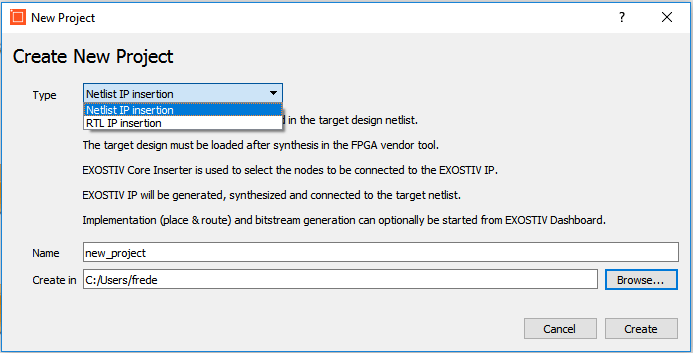
You can choose the flow when creating a new project with EXOSTIV Dashboard software.
This choice has got consequences on the output files, on the results of the core insertion process and on the operations that you need to execute for obtaining an instrumented design.
See the table below:
RTL flow
- Manual core insertion in RTL code
- EXOSTIV IP is not linked to specific nodes
- Nodes names are mapped during analysis
- Requires synthesis, place & route and bitstream generation after insertion
- Produces: a netlist of EXOSTIV IP, a RTL instantiation template and pinout / timing constraints
Netlist flow
- Automatic core insertion in Netlist
- EXOSTIV IP is linked to nodes selected from the design
- Nodes names are mapped during EXOSTIV IP generation
- Requires place & route and bitstream generation after insertion
- Produces: an instrumented design netlist and optionally, a fully placed and routed design
The RTL flow…
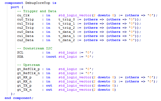
…produces a generic debugging IP with the chosen resources and generic input port. The process of configuring EXOSTIV IP in EXOSTIV Dashboard is merely a matter of choosing the number of capture units in the IP and the width of them (see for instance an example of such IP component declaration in VHDL below). The generated modules will have ports numbered as: ‘cu0_Trig’ or ‘cu2_Data’.
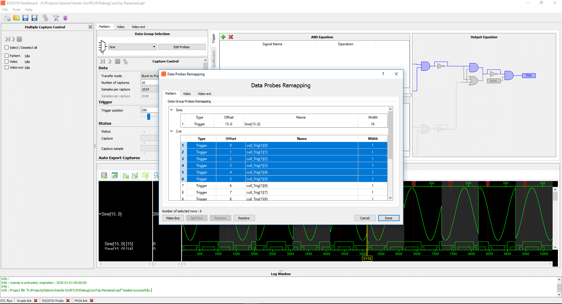
Once generated, you can connect EXOSTIV IP to any RTL signal / wire from your RTL code.
Once the IP is connected in the target design RTL code and once the synthesis, P&R have run, the EXOSTIV IP inputs really have a functional meaning. It is then desirable to specify a logic name rather than an obscure ‘cu#_Trigger(0)’. It just eases analysis. So, this will be done in the analyzer, with the ‘Data Probes Remapping’ function (see screenshot below).
Typically, the RTL flow will be used when:
- The same sets of nodes are observed for debugging. This would be the case for a AXI bus-based system, where debugging the system requires watching the AXI bus traffic.
Typically, this supposes that there is little or no iteration for selecting the nodes observed during debug. - Interesting nodes are optimized, removed or renamed after synthesis, preventing from probing them. In such a case, the RTL flow gives a better ‘insurance’ to be able to watch interesting nodes. Using properties on signals such a ‘MARK_DEBUG’ for AMD Vivado™ or ‘SYN_KEEP’ for Synplify would, however, limit the risk of ‘loosing’ the interesting nets after synthesis.
The Netlist flow…
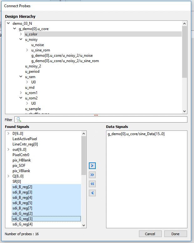
… uses a communication between the FPGA vendor tool and EXOSTIV Dashboard software to dig into the design hierarchy, extract nodes and clock information from the synthesized design (see the node selection window below).
Typically, the Netlist flow will be used when:
- You want to save the time of design synthesis when a new EXOSTIV IP core is generated. This would be the case when successive core insertions must be run to track bugs.
- You do not want to manually modify the RTL code – which can be time-consuming. Leaving the work of inserting and connecting EXOSTIV IP to EXOSTIV Dashboard software and the FPGA vendor tool suite proves extremely efficient.
Takeaways
EXOSTIV Dashboard and Exostiv Blade Core Inserter flows are 2 alternate ways of generating and inserting EXOSTIV (or Exostiv Blade) IP into your target design. Which one is right for you very much depends on your habits and the flow you are using for creating and debugging FPGA.
It would be too quick to dismiss the RTL flow because it is not fully automated – and requires editing the RTL code to bring the right ‘wire connections’ at the level where the IP is instantiated. The RTL flow fits well when the same specific nodes are systematically probed. Using scripts with conditional instantiation of IPs is a very efficient way to generate and debug designs based on a RTL approach. For Exostiv Blade, which supports more complex systems, multiple IPs inserted into single and multiple FPGA, users might prefer building whole libraries of Exostiv Blade IPs ready for insertion (even conditionally) into RTL. In addition, coding techniques exist for easing the work of wiring nodes across the hierarchy (such as this one for VHDL, for instance).
Similarly, you should think again before dismissing the Netlist flow because node names cannot be found after synthesis: some properties can be used to limit this effect – and we’ll come back on this later. The integration of EXOSTIV and Exostiv Blade with the FPGA vendor tool allows browsing the design hierarchy, selecting nodes to observe and then automatically generate an instrumented design. When available*, the Netlist flow can be a wonderfully productive approach for debug.
Thank you for reading.
– Frederic
*The Netlist flow is currently available for AMD FPGA only.