Search
Exostiv Core Inserter Overview
This article applies to Exostiv Blade and Exostiv Probe type ‘EP16000’, used with software environment v2 (DARK).
Exostiv Core Inserter is used to generate the Exostiv IP cores used to capture data from inside FPGA chips with Exostiv Blade and Exostiv Probe.
This application is installed on Windows and Linux workstations and uses the target FPGA vendor tool, which must be installed separately (not provided).
Exostiv Core Inserter provides the following features:
[custom_list]
- Libraries of the supported FPGA parts with pinouts and capabilities;
- Controls to set up the connectivity with Exostiv Blade or Exostiv Probe;
- Controls to set up Exostiv IP capture options and features;
- Controls to run Exostiv IP generation and insertion.
[/custom_list]
Exostiv IPs – Overview
[one_half]
[message]
Standard IP
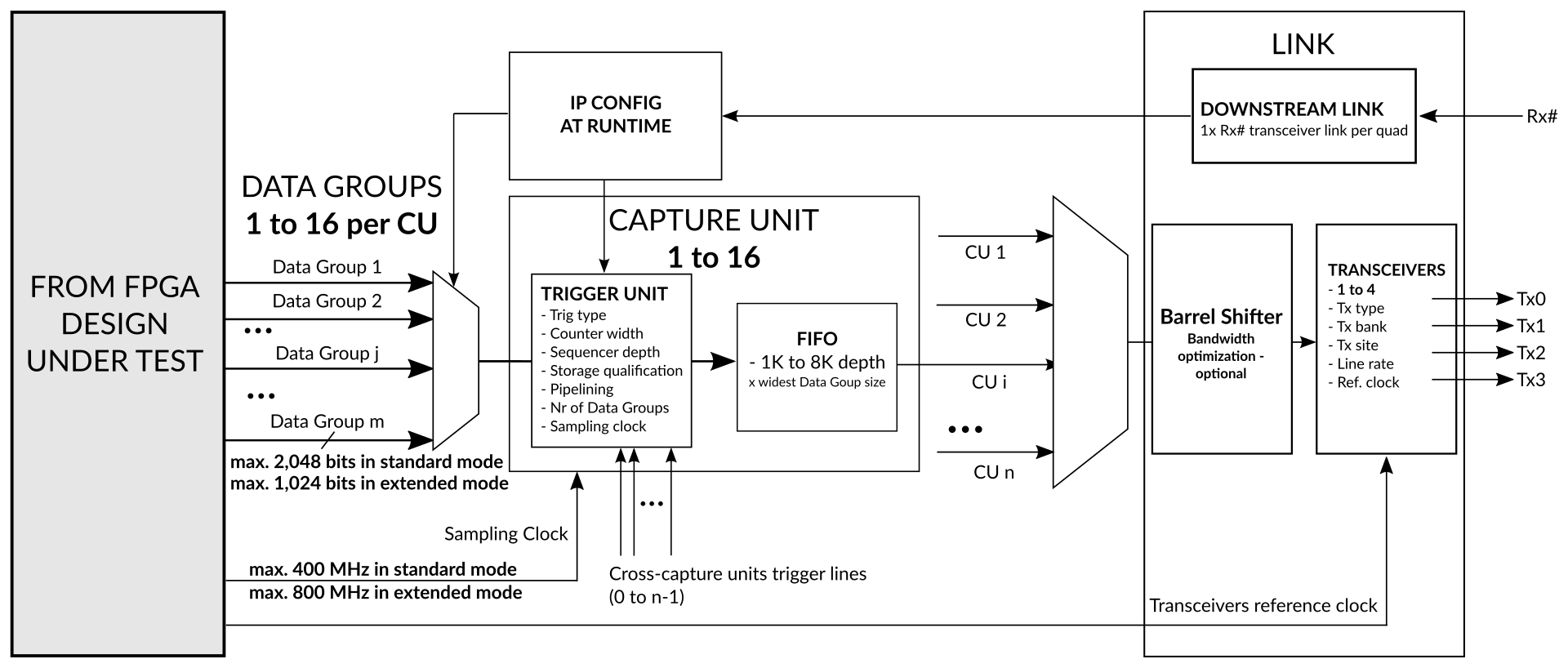
Main features include:
[custom_list]
- Multiple capture unit with distinct sampling clock source
- Sampling up to 800 MHz
- Up to 16 x 2K bits simult. sampling per IP core instance
- Multiple data groups with dynamic selection at runtime
- Dynamic triggering and data qualification conditions selection
- Cross-clock domain triggering
- Trigger positioning across the whole Exostiv Probe capture memory
- BRAM-based and Streaming (DDR based) modes of captures
[/custom_list]
[/message]
[/one_half]
[one_half_last]
[message]
Extended Width IP
Available from software 2.1.0 build 250314. This update will be released for Exostiv Blade first, then for Exostiv Probe (EP16000). Important: using this IP requires a Blade update as part of our maintenance service – contact us for details.
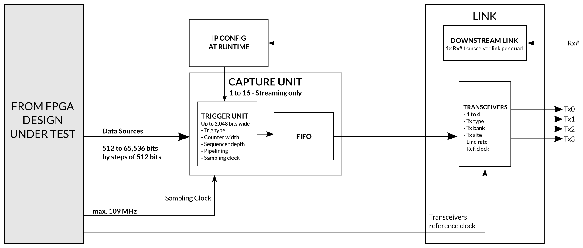
Main features include:
[custom_list]
- Single capture unit to minimze resources and increase reach.
- Sampling up to 109 MHz
- Up to 65K bits simult. sampling per IP core instance
- Dynamic triggering
- In / Out trigger with adjustable input trigger delay for multiple IP chaining
- Trigger positioning across the whole Exostiv Blade capture memory
- Simplified streaming (DDR based) mode of capture
- Extremely small footprint
[/custom_list]
[/message]
[/one_half_last]
If Exostiv Blade is used as a hardware, multiple Exostiv Core Inserter IP instances can be generated for insertion into one or multiple FPGAs. Because each Exostiv IP instance uses transceivers from the same target FPGA quad, there will be as many physical connections between the target system and the Exostiv Blade unit as there are Exostiv IP instances. Each distinct Exostiv IP instance has to be generated with Exostiv Core Inserter software.
Exostiv IP generated with Exostiv Core Generator are also compatible with Exostiv Probe ‘EP16000’ model, if the chosen data rate on the transceiver does not exceed 16.25 Gbps.
[divider]
Exostiv Core Inserter – Welcome screen
The welcome screen provides shortcuts to create or load project files (extension .bpf), in addition to license controls and direct access to online documentation (such as this article).
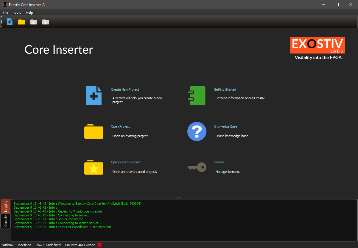
When creating a new project file the type of insertion flow is chosen:
[custom_list]
- Netlist insertion flow: generates the Exostiv IP instance and inserts it automatically into the target synthesized FPGA loaded in Vivado.
- RTL insertion flow: generate the Exostiv IP instance with a template and constraint files ready for insertion into VHDL or Verilog code.
[custom_list]
For more information about the netlist and RTL insertion flows, please refer to the following article: RTL or netlist flow?.
[divider]
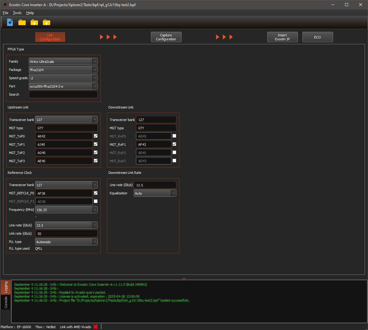
Exostiv Core Inserter – Link configuration
The ‘link configuration’ page defines the target FPGA for the generated IP and how it connects to Exostiv Blade or to Exostiv Probe. This information is fully available in the specifications of the target FPGA board – and how it is set up.
The parameters are:
[custom_list]
- FPGA Type: FPGA family, package, speed grade, part number.
- Upstream link: defines the bank, the number and the pin location of the transceivers used to connect the generated IP to Exostiv Blade or Exostiv Probe.
- Downstream link: defines which of the chosen transceivers is used for the ‘downstream channel’ from Exostiv Blade or Exostiv Probe to the IP.
- Reference clock: transceiver source clock characteristics. Location, frequency, derived line rate and PLL parameters.
- Downstream link rate: some information and parameters about the downstream link.
[/custom_list]
[divider]
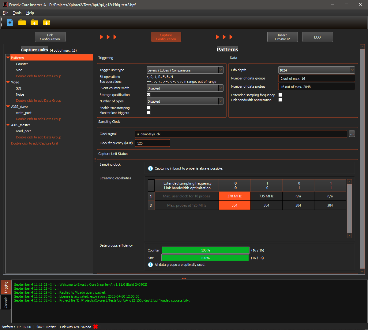
Exostiv Core Inserter – Capture configuration
Standard IP
The ‘Capture Configuration’ screen provides the settings that define the resources of the IP used to capture (sample) data from inside the FPGA:
[custom_list]
- The list of ‘capture units’ and the multiplexed data groups connected to each of them;
- For each capture unit, the allocated resources: trigger machine complexity, additional trigger counter and data qualification, capture unit FIFO / in FPGA buffer size, optional transceiver bandwidth optimization resources (barrel shifter).
- Sampling clock signal source (netlist mode) and frequency;
[/custom_list]
Moreover, the ‘capture configuration’ screen provides an analysis of the chosen option, and how they allow streaming data to the Exostiv Blade or Exostiv Probe, provided the number of transceivers and their data rate (burst mode is always possible). For more information about the ‘stream to probe’ and ‘burst to probe’ modes, please check this article.
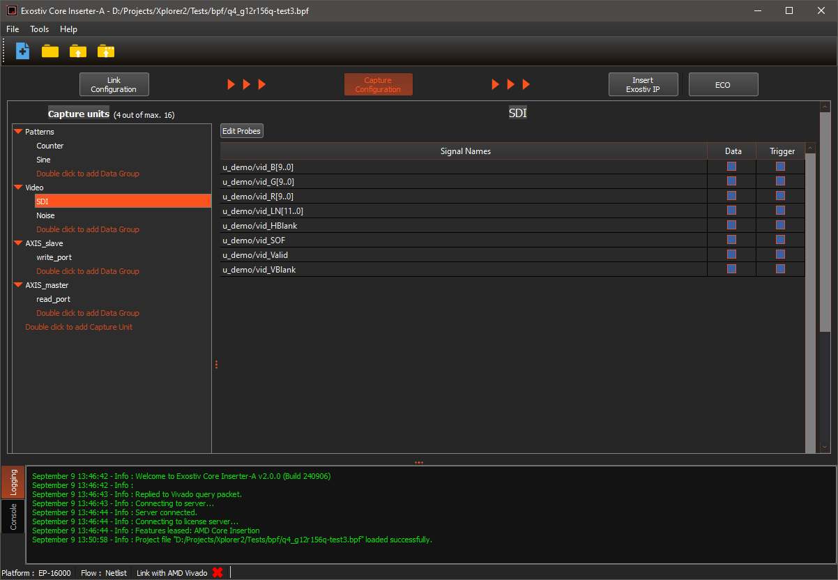
Selecting one of the data groups in netlist mode of insertion displays the controls to select the nodes to be observed from the synthesized design loaded in Vivado.
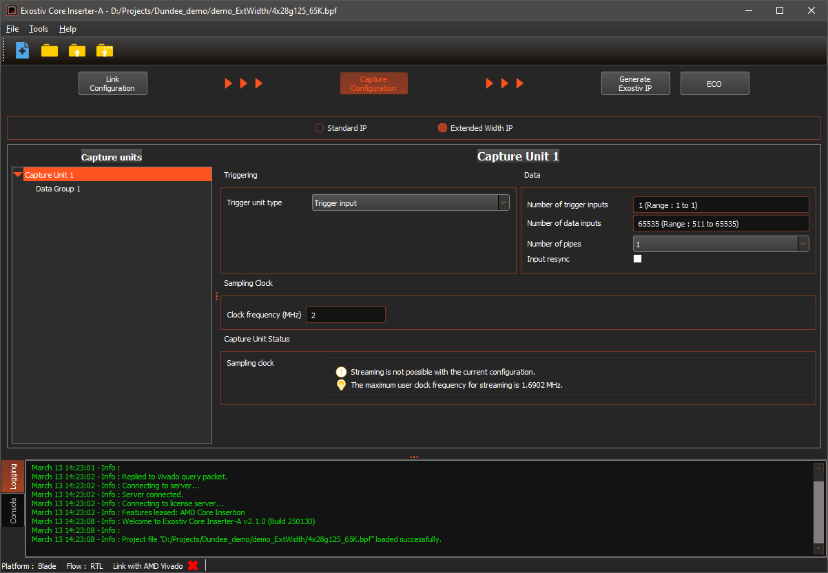
Extended width IP
The ‘extended width IP’ aims at capturing up to 65k nodes for one IP instance. It is a lightweight IP with simplified trigger resources and capture unit resources, as it features a single trigger line input, a single capture unit and a single data group. The ‘Extended width IP’ is selected with the top radio button available from Exostiv Core Inserter version 2.1.0 build 250130.
[divider]
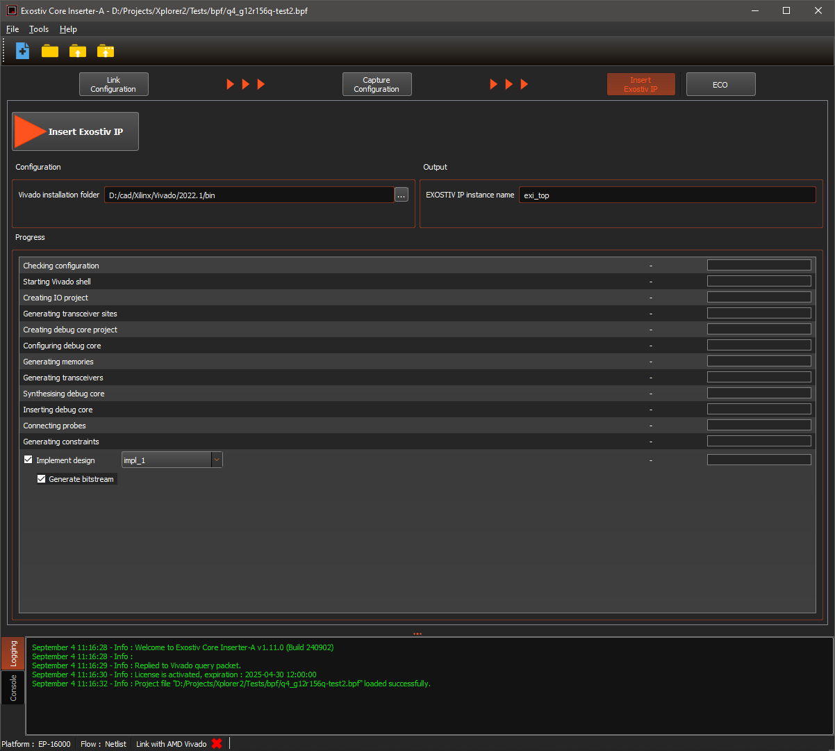
Exostiv Core Inserter – Core Generation and Insertion
Finally, the last screen, which depends on whether netlist or RTL mode of insertion is used, allows running the following:
[custom_list]
- RTL mode: generates an Exostiv IP as configured and provides it as a synthesized netlist with additional files (wrappers, constraints, scripts). Please refer to the following article to learn about the files generated in RTL insertion flow by Exostiv Core Inserter: Xilinx FPGA: which files are produced in RTL flow and how do I use them?
- Netlist mode: generates an Exostiv IP as configured, inserts it into the synthesized design loaded into Vivado and connects the nodes chosen for observation. Optionally runs implementation (place and route) and bitstream generation.
[/custom_list]
IP generation / insertion requires a proper reference to the FPGA vendor tool path, as well as specifying a name for the generated instance. ‘Cache controls’ are also available – they allow maintaining a list of previously generated IP cores to avoid generating again a core that was previously generated with identical settings.